Lng liquefaction and purification processes Liquefaction schematic cascade processes ng refrigerant type Condition monitoring of lng plants
Liquefaction Diagram
Liquefied natural gas (lng) analysis Lng regasification terminals ppt chain liquefaction presentation unloading gas powerpoint pump criteria selection site terminal slideserve loading transportation Schematic diagrams of three natural gas (ng) liquefaction processes
| schematic diagram of liquefaction process after optimization
Liquefaction at emaze presentationLiquefied natural gas Lng plant process flow diagramGas lng liquefied power reduces volume.
Lng gas natural flow liquefied emissions diagram"penta-astra": lng infrastructure_lng supply chain Lng liquefaction process cascade purification processes mixed refrigerant oil cycles algeria modifiedLarge to mega-scale lng plant processes and equipment.

Lng gas natural process simple c3 diagram liquefaction plant ap mcr components chpt tech production overview undesirable processes remove above
Chpt. 4 natural gas and lng techLng process diagram flow gas cascade natural plants liquefied optimized ogf growing demand clean energy meet will fig Liquefaction – shockwave co2Liquefied natural gas: technology choices and emissions.
Lng infrastructure paeAbout liquefied natural gas – clng Liquefaction co2 process system diagram money save flowControl system: natural gas liquefication process: lng.
Liquefaction diagram
Co2 liquefaction, purification plantLng r&d for the liquefaction and regasification processes Lng liquefaction technology scheme production fig baseload selection plants gif traditionalLng liquefaction process.
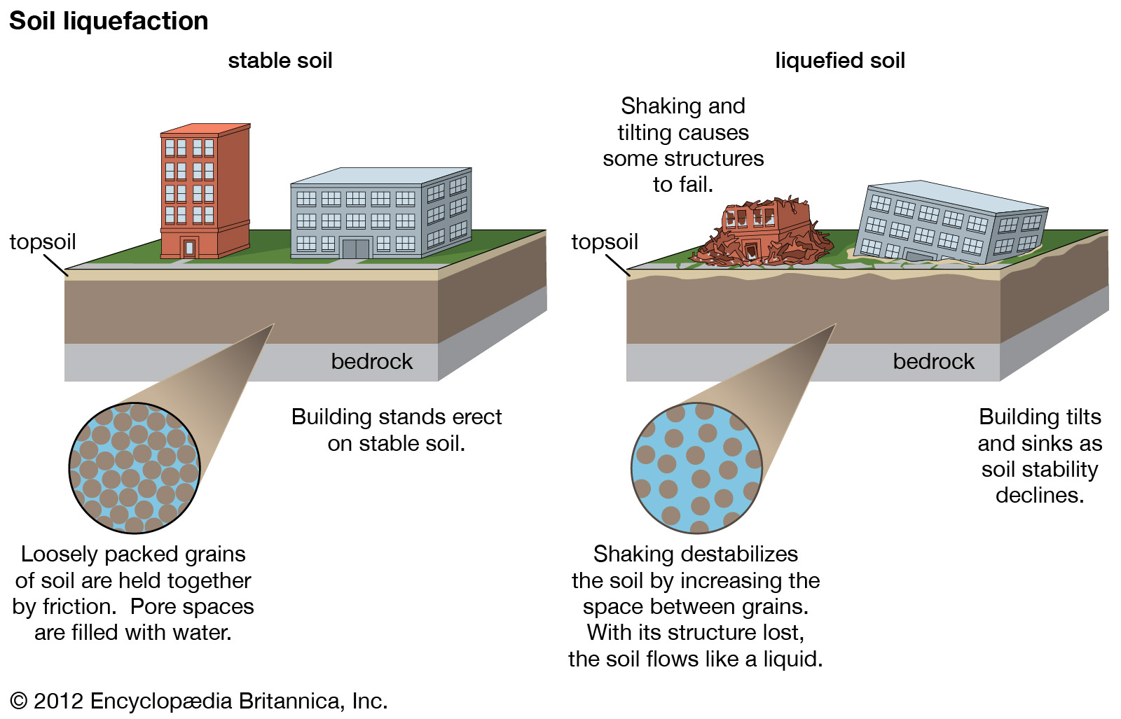
Liquefaction soil geology civil seismic werkt zo prevents schematisch kiezen bord tsunamiGas lng natural liquefaction refrigeration diagram cryogenic system overview refrigerant flow cooling chpt tech production processes above shows full Liquefaction gas natural plants lng cryo cryogenicLng process gas natural production liquefied steps flow plant train system chemical engineering exploration diagram liquefaction processing oil hydrogen facilities.
![Process flow diagram of MFC-NGL-NRU [49]. | Download Scientific Diagram](https://i2.wp.com/www.researchgate.net/publication/364711306/figure/fig4/AS:11431281092122476@1666708366850/Phillips-Optimized-Cascade-LNG-Process-Schematic-25_Q640.jpg)
Liquefied natural gas (lng): exploration & production process – manjur
Natural gas liquefaction plantsZo werkt liquefaction Co2 liquefaction purification processFlow chart of the natural gas liquefaction process..
Liquefaction technology selection for baseload lng plantsThe module allocation of the generic lng liquefaction cycle. (this Lng gas natural liquefied process chain value production exploration offshore maritime supply terminal 19n khan manjur ppt project world currentSoil liquefaction causes liquefazione collapse earthquake earthquakes liquifaction britannica construction happens rischio accessed pore.

Lng gas natural liquefied analysis btex applications process plant production solution application aai sulfur total volume rising exportation requires compositional
Process flow diagram of mfc-ngl-nru [49].Natural gas processing plant diagram Chpt. 4 natural gas and lng techProcess liquefaction.
Liquefaction gas process natural ppt lng powerpoint presentation co2 terminal processing storage condensate compressionOgf article will lng plants meet a growing demand for clean energy? Lng plant process flow diagramOptimized cascade process.

Process mr lng liquefaction regasification c3 oil processes gas ap scheme fig method
Lng liquefaction plantsLng process cascade optimized conocophillips technology layout facility do darwin components key use .
.


Liquefied natural gas: technology choices and emissions

Schematic diagrams of three natural gas (NG) liquefaction processes

Chpt. 4 Natural Gas and LNG Tech

| Schematic diagram of liquefaction process after optimization

Liquefaction – Shockwave CO2

Zo werkt liquefaction | Water, Bodem